Even the simplest thing we recognize may seem increasingly difficult in another point of view. Take a simple arithmetic operation for example, if one wants to calculate the function y = ax + b with given a and b, he simply multiplies any number x with a, then adds b, and gets the answer. What if no multiplication and addition can be used? How can the calculation even be possible?
Computers can actually finish the task by implementing three fundamental logic operations: AND, OR, and NOT. Most of them can do these operations within a nanosecond. In this project, I constructed a circuit for performing a simple linear algebra calculation (Fig. 1) using only basic logic and storage circuits (Fig. 2) that can be realized using standard cells.

Figure 1. Formula to be calculated. (x0, x1, x2 are all 6 bit 2’s complementary integers)

Figure 2. Basic logic and storage circuits. (Note that other circuits (e.g. NAND, XOR) are also used in this project)
Here, x0, x1 and x2 equal the three 6-bit integer inputs (2’s complementary), so there are a total of 18 Boolean input values. The output is stored in a 16-bit integer. Therefore, the goal for this project is to construct a circuit that connects all of the 18 inputs and the 16 outputs, and perform the calculation.
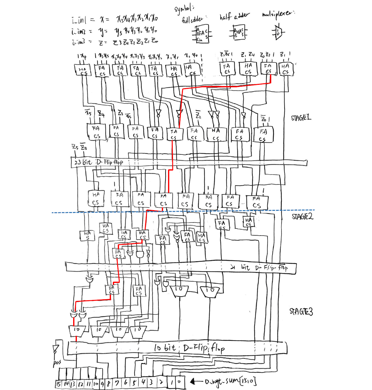
To make it harder, three stages of pipelines are carried out. This means that calculations are divided into three parts, and the most time-consuming part contains the critical path of the whole circuit. Fig. 3 shows an illustration of the designed circuit.

Figure 3. Logic circuit diagram for realizing the arithmetic operation (Fig. 1) of this project.
Verilog is used for simulating the results, and the circuit is written as a spice sub-circuit model. Because the D flip-flop is used, the critical time is defined as the clock cycle of the D flip-flop. Moreover, the number of transistors are defined for every basic logic circuit, so the total number of transistors can be calculated, and is named the “area” of the whole circuit.
Fig. 4 shows the simulation results of the circuit. It can be seen that only 1.3305 nanosecond is used for a half clock cycle of the circuit. This means that the circuit can continuously output calculation results every 2.661 nanosecond, which is really fast!

Figure 4. Simulation results using Verilog.
Having the experience of using absolutely no arithmetic operations for calculating a linear algebra problem really significantly broadened my insight towards digital IC design. This project inspired me to understand that even the most insignificant elements possess the potential to be combined and make up the world that we live in.