Category: Graduate

Lab Website
Linear Algebra Calculation using Integrated Circuits
Even the simplest thing we recognize may seem increasingly difficult in another point of view. Take a simple arithmetic operation for example, if one wants to calculate the function y = ax + b with given a and b, he simply multiplies any number x with a, then adds b, and gets the answer. What if no multiplication and addition can be used? How can the calculation even be possible?
Computers can actually finish the task by implementing three fundamental logic operations: AND, OR, and NOT. Most of them can do these operations within a nanosecond. In this project, I constructed a circuit for performing a simple linear algebra calculation (Fig. 1) using only basic logic and storage circuits (Fig. 2) that can be realized using standard cells.

Figure 1. Formula to be calculated. (x0, x1, x2 are all 6 bit 2’s complementary integers)

Figure 2. Basic logic and storage circuits. (Note that other circuits (e.g. NAND, XOR) are also used in this project)
Here, x0, x1 and x2 equal the three 6-bit integer inputs (2’s complementary), so there are a total of 18 Boolean input values. The output is stored in a 16-bit integer. Therefore, the goal for this project is to construct a circuit that connects all of the 18 inputs and the 16 outputs, and perform the calculation.
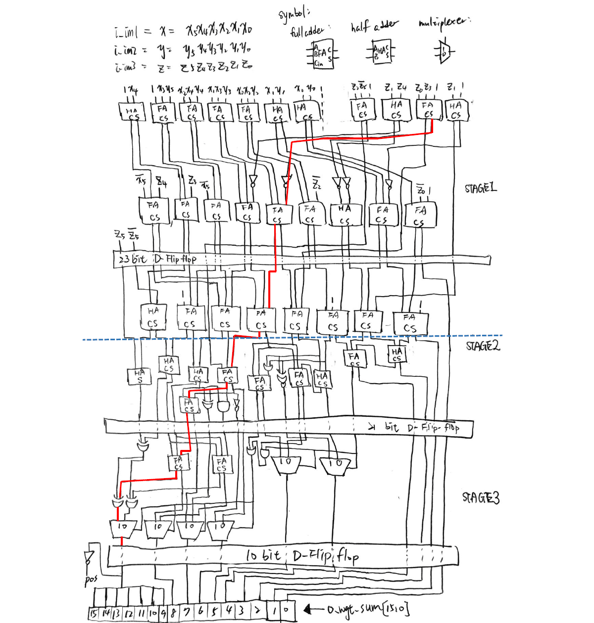
To make it harder, three stages of pipelines are carried out. This means that calculations are divided into three parts, and the most time-consuming part contains the critical path of the whole circuit. Fig. 3 shows an illustration of the designed circuit.

Figure 3. Logic circuit diagram for realizing the arithmetic operation (Fig. 1) of this project.
Verilog is used for simulating the results, and the circuit is written as a spice sub-circuit model. Because the D flip-flop is used, the critical time is defined as the clock cycle of the D flip-flop. Moreover, the number of transistors are defined for every basic logic circuit, so the total number of transistors can be calculated, and is named the “area” of the whole circuit.
Fig. 4 shows the simulation results of the circuit. It can be seen that only 1.3305 nanosecond is used for a half clock cycle of the circuit. This means that the circuit can continuously output calculation results every 2.661 nanosecond, which is really fast!

Figure 4. Simulation results using Verilog.
Having the experience of using absolutely no arithmetic operations for calculating a linear algebra problem really significantly broadened my insight towards digital IC design. This project inspired me to understand that even the most insignificant elements possess the potential to be combined and make up the world that we live in.

Robot Arm Control
It’s easy for us to point at a certain coordinate in space. That’s mainly because we simply locate the point with our eyes, and continuously check if our finger is pointing at that very spot. It surely will be more difficult without using eyes, and this is the case for robot arm control with no image feedback.
Think of a two arm robot (Fig. 1). We usually want to reach a certain point on the x-y plane. The problem is only the angle of the joints can be controlled. How can we correlate the joint angles of a robot with its tip coordinate? Things get harder when it comes to 3D space, and even harder considering its rotation.
In this project, I created a program that can calculate the every joint angle of the 6-arm robot IRB140 for positioning it at a given (x, y, z) coordinate and rotation.

Figure 1. Dimensions of the IRB140 robot (unit: mm) [1].
The problem for reversing an operation from the specified coordinate and rotation to every rotation angle of an arm joint lies in the field of inverse manipulator kinematics. There may be multiple solutions that lead to the same result. Thus, I implemented the Pieper’s solution [2] for solving the joint angles for the IRB140 robot.
Here’s a video demonstration for precision control of the IRB140 by only giving the joint angles as the input. The robot follows a trail surrounding a paper box with the tip of the last arm always pointing at the center of the box.
[Source code for robot arm control program]
1. ABB, IRB140 product specification, 2019, https://library.e.abb.com/public/2893a5756d204e19aba0d37c2a2cadc6/3HAC041346%20PS%20IRB%20140-en.pdf
2. Craig, J.J., Introduction to Robotics: Mechanics & Control. 1986: Addison-Wesley Publishing Company.
Heat Transfer Dynamic Plotting
It may often be increasingly hard to comprehend dynamic properties using only static figures shown on a textbook. There is more need for data visualization for better understanding the complicated world around us…
This is a demo program that I have written in a course of heat transfer. I served as the teaching assistant and assisted my professor for delivering the curriculum. In order to let the students understand some time-dependent properties between the temperature and position of a heat transferring process, I used Python and the library Matplotlib for customized visualization of the heat transfer process.
Compared with a static plot of the same process (Fig. 1), this dynamic plot (Fig. 2) intuitively demonstrated the nature of temperature change according to time.
Figure 1. Static plot of normalized temperature (1-Φ) vs normalized position (η) at different normalized time (τ) using OriginLab.
Figure 2. Dynamic plot of heat transfer.

T-Rex Game

This is a simplified game mimicking the T-Rex dino game appearing on the “No Internet” google page. The motivation for making this comes from a YouTube video where a program learns to play the game at superhuman level using genetic algorithm. It was quite fascinating knowing the fact that nothing has to be taught in order to let this program acquire the ability to jump over obstacles, dodge birds … etc.. I made this game using C, with the console being the gameplay screen. However, due to the fact that characters instead of figures were drawn, the screen will always be in a flickering condition for renewing the screen at a rate such quickly.

Blackjack

Blackjack is a well-known gambling game and is the most widely played casino game in the world. Numerous researches about this game had been carried out, including machine learning of optimal actions for playing the game (see reinforcement learning for solving Blackjack).
I got particularly interested in machine learning during graduate school. Thus, I made this simple Blackjack game program in order to construct a game environment for reinforcement learning of game agents for future work.
The game process is a single round of Blackjack, starting from player 0 being dealt 2 cards from the dealer. The player can either choose to “hit”, “stand” or “split” according to his cards. After the “stand” action is chosen or if he goes busted, The next player follows on.
I wrote this game using C language, which runs on a command prompt. While being simple, It can provide useful insights to game agents which can further learn on its own for achieving optimal behavior.