Author: andrewlai61616
I’m an active person with strong learning abilities, being profoundly inspired by programming when I was young. In junior high school, I self-learned Visual Basic 6.0 for making simple programs and won first prize in science fair competition. In senior high school, I learned C language along with algorithms and data structures, and won 5th ~ 10th place in Taiwan Olympiad in Informatics. These series of events firmly established my outstanding programming skills.
In college, I majored in mechatronics and attained relevant skills for various applications. I teamed up with schoolmates for developing an alarm clock that can awake people using a specific fragrance and earned 40,000NTD in a fundraising event. During this period, I acquired PCB layout skills and the ability for practical usage of microcontrollers, IC chips and different electronic components. I have lots of practical experiences for machine learning and data mining using neural networks (Python + Tensorflow), and won first prize in a competition held by Taiwan Semiconductor Manufacturing Company (Big Data Analytics for Semiconductor Manufacturing). I also have experience in designing digital logic circuits using Verilog and Hspice, and obtained high scores in class.
My graduate research topic focuses on interdigitated array electrode chips applied to electrochemical impedimetric biosensing. I learned the complete microfabrication process for microelectrodes and microfluidic chips, utilized Raspberry Pi for developing a wireless and miniaturized website-controlled impedance detection device, and applied those to my own research. Accordingly, I wrote a full research article as first author, and published it on an international journal (Electrochimica Acta, IF = 5.383) (DOI: 10.1016/j.electacta.2019.134629). Now, I currently work as research assistant in my lab, and take the lead in research and development.
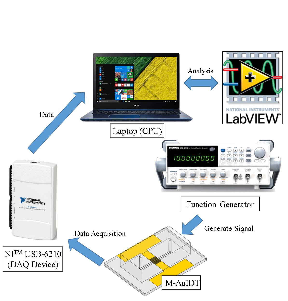
Real-time Impedance Detection System α

Lab Website
Linear Algebra Calculation using Integrated Circuits
Even the simplest thing we recognize may seem increasingly difficult in another point of view. Take a simple arithmetic operation for example, if one wants to calculate the function y = ax + b with given a and b, he simply multiplies any number x with a, then adds b, and gets the answer. What if no multiplication and addition can be used? How can the calculation even be possible?
Computers can actually finish the task by implementing three fundamental logic operations: AND, OR, and NOT. Most of them can do these operations within a nanosecond. In this project, I constructed a circuit for performing a simple linear algebra calculation (Fig. 1) using only basic logic and storage circuits (Fig. 2) that can be realized using standard cells.

Figure 1. Formula to be calculated. (x0, x1, x2 are all 6 bit 2’s complementary integers)

Figure 2. Basic logic and storage circuits. (Note that other circuits (e.g. NAND, XOR) are also used in this project)
Here, x0, x1 and x2 equal the three 6-bit integer inputs (2’s complementary), so there are a total of 18 Boolean input values. The output is stored in a 16-bit integer. Therefore, the goal for this project is to construct a circuit that connects all of the 18 inputs and the 16 outputs, and perform the calculation.
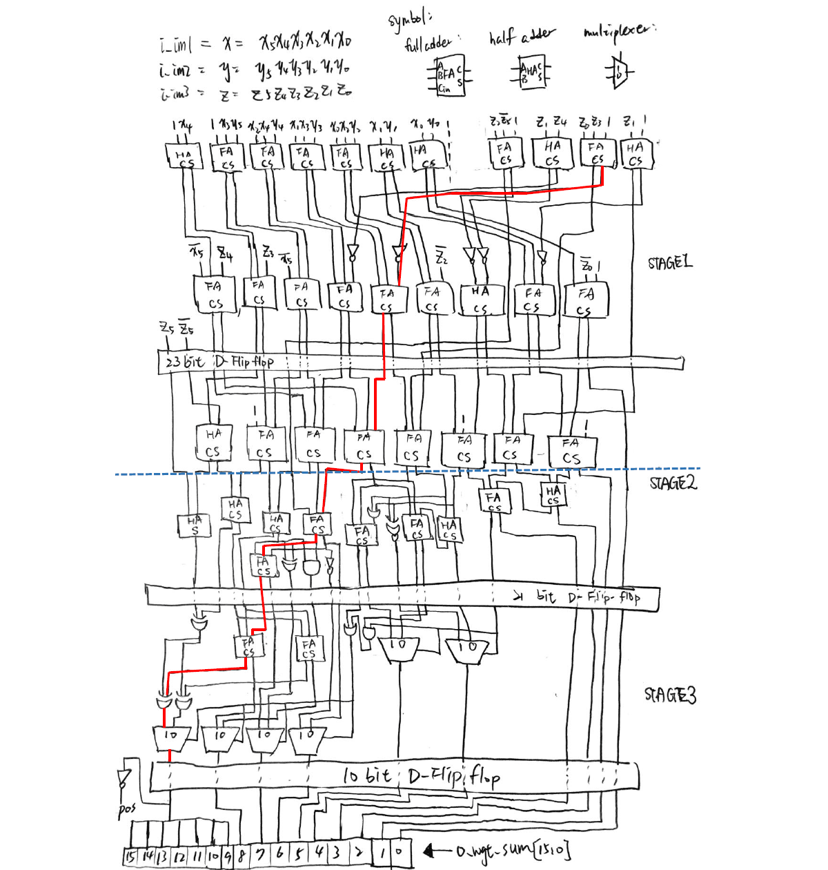
To make it harder, three stages of pipelines are carried out. This means that calculations are divided into three parts, and the most time-consuming part contains the critical path of the whole circuit. Fig. 3 shows an illustration of the designed circuit.

Figure 3. Logic circuit diagram for realizing the arithmetic operation (Fig. 1) of this project.
Verilog is used for simulating the results, and the circuit is written as a spice sub-circuit model. Because the D flip-flop is used, the critical time is defined as the clock cycle of the D flip-flop. Moreover, the number of transistors are defined for every basic logic circuit, so the total number of transistors can be calculated, and is named the “area” of the whole circuit.
Fig. 4 shows the simulation results of the circuit. It can be seen that only 1.3305 nanosecond is used for a half clock cycle of the circuit. This means that the circuit can continuously output calculation results every 2.661 nanosecond, which is really fast!

Figure 4. Simulation results using Verilog.
Having the experience of using absolutely no arithmetic operations for calculating a linear algebra problem really significantly broadened my insight towards digital IC design. This project inspired me to understand that even the most insignificant elements possess the potential to be combined and make up the world that we live in.

Robot Arm Control
It’s easy for us to point at a certain coordinate in space. That’s mainly because we simply locate the point with our eyes, and continuously check if our finger is pointing at that very spot. It surely will be more difficult without using eyes, and this is the case for robot arm control with no image feedback.
Think of a two arm robot (Fig. 1). We usually want to reach a certain point on the x-y plane. The problem is only the angle of the joints can be controlled. How can we correlate the joint angles of a robot with its tip coordinate? Things get harder when it comes to 3D space, and even harder considering its rotation.
In this project, I created a program that can calculate the every joint angle of the 6-arm robot IRB140 for positioning it at a given (x, y, z) coordinate and rotation.

Figure 1. Dimensions of the IRB140 robot (unit: mm) [1].
The problem for reversing an operation from the specified coordinate and rotation to every rotation angle of an arm joint lies in the field of inverse manipulator kinematics. There may be multiple solutions that lead to the same result. Thus, I implemented the Pieper’s solution [2] for solving the joint angles for the IRB140 robot.
Here’s a video demonstration for precision control of the IRB140 by only giving the joint angles as the input. The robot follows a trail surrounding a paper box with the tip of the last arm always pointing at the center of the box.
[Source code for robot arm control program]
1. ABB, IRB140 product specification, 2019, https://library.e.abb.com/public/2893a5756d204e19aba0d37c2a2cadc6/3HAC041346%20PS%20IRB%20140-en.pdf
2. Craig, J.J., Introduction to Robotics: Mechanics & Control. 1986: Addison-Wesley Publishing Company.

Temperature and Humidity Sensor
This is a homework in class where we are assigned to utilize the temperature and humidity sensor DHT11 and an LCD display. Once activated, the LCD display will show either the temperature or the humidity being detected by the sensor. A button can be pressed to switch between temperature and humidity display.
Complex functionality can be achieved by including pre-coded libraries for controlling these components using Arduino, the development board I had used.
Though being a very simple project, such components serve as the simple building block for constructing a sophisticated hardware system. Therefore, this project plays an important role in the initial stage of hardware design for me.
Here’s a simple control process demonstration:

Bladeless Fan
The Dyson cooling fan is an eye-catching product. At first sight, some people may wonder how the seemingly bladeless fan really works because it simply looks like a structure with no air outlet. The fact is it can does have a small outlet at the inner part of its “ring”, and has the ability to take fluid dynamics into practice and enhance the air flow, making it also an air multiplier.

Figure 1. Dyson bladeless fan and simulated air flow.
In fluid dynamics class, I and a classmate of mine decided to construct a bladeless fan by our own and study the air multiplying phenomenon. We used 3D printing to fabricate the “ring” part of the fan, and a small centrifugal fan for connecting with the inlet of the ring part and inject a strong current inside.

Figure 2. Illustration and photograph of the bladeless fan.
Now we wanted to simply test whether this structure really leads to an air multiplying effect. We divided the outlet are into 9 sections, which can be represented using a 3×3 rectangular grid, and calculated the wind speed of every section at different input voltages for the centrifugal fan.
Fig. 3 shows the air velocity profile of the output wind, and Fig. 4 shows the magnification of air flow.

Figure 3. Air velocity (t_m [=] m/s) of 3×3 section grid at different input voltages.

Figure 4. Magnification of air flow at different input voltages of the centrifugal fan.
During this project, I learned more about the fundamentals of fluid mechanics, and memorized the relevant rules more deeply, which made me have a better understanding of this subject.

Path Following Car
Guess the Number (iOS)
This is the first iOS game I had made using Xamarin, and is the second project of the guess the number series (after Guess the Number (Windows) and prior to Guess the Number AI). (The two-player game is also named Bulls and Cows.)
At the start of the game, a random 4-digit code is generated by the app and the player starts to guess that code. The player can restart the game anytime by pressing RESET, and a history of guesses and results are shown in a list at the bottom.
Here’s a demonstration of the app:
Considerations for app development are quite different from computer programs, such as the different screen sizes for different mobile platforms, and most of the time only a touch screen can be used. After finishing this project, I acquired some important fundamental concepts and know-hows for app design.
Guess the Number AI
After completing the first two projects of the Guess the Number series (Guess the Number (Windows) and Guess the Number (iOS)), I made an AI that can play this game at a high-human level.
It has been proven that at most 7 turns are needed to guess the answer, with a best average game length of 5.21 turns. For this game, all the possible combinations (e.g. “0123”, “7381” …) can be saved into a 1D array. After each guess, the possible combinations for the answer will be reduced. Therefore, the algorithm of the program is written for finding a number that will minimize the maximum possible combinations left. The time complexity for each turn is O(n3), and an average of 5 turns of guessing if needed for an arbitrarily chosen number.
For using the program, the user must first choose a 4-digit answer (e.g. “0123”), and input the two numbers [A] and [B] according to the game rules and the numbers guessed by the program. For instance, if the answer is “1357”, and the AI guesses “3127”, the user must input 1 2 ([A] = 1, [B] = 2).
Here’s a demonstration of the AI program guessing the answer “8192” in 5 guesses: