Automated Forex Trading System

I acquired my first forex bank account for attending an international conference in 2018. Lacking the basic concepts for fundamental and technical analysis, I came up with a simple but profound idea: Would it be possible to construct a system that can automatically trade forex and profit from it? Thus started this project of automated forex trading.

System Framework

Fig. 1 illustrates the overall system architecture. Here, the main server is used to autonomously access online forex data, save it into a table, and perform all necessary calculations for generating a trade signal (e.g. buy, sell, do nothing). A trading model is loaded inside the main server, and can be any form of structure as long as it can input history and current forex data and output a trade signal. A client can train the trading model on a remote server, then manually update it on the main server. The trade signal is sent to another server specialized for interacting with an online trading platform.

Figure 1. System architecture of this project.

This architecture has the advantage for clearly distinguishing the functional blocks, where each block can be modified separately. For example, if one plans to implement a trading strategy that utilizes machine learning for prediction of future prices, he/she can pre-train the model beforehand, update the model to the main server, and needn’t worry about system failure as long as the input and output of the trading model corresponds to what the main server requires.

Fig. 2 details the flowchart for the main and transaction server. The servers initialize, connect with each other and other online resources, and enter the main loop for autonomous trading. The main server runs on a Linux-based operating system, where Python is used as the language for the main program. By constructing a database and querying with MySQL, per-minute forex data can be stored structurally. For the transaction server, Python is also used for the main program, and Selenium is used for web control automation. The two servers communicated using SSH protocol.

[Source Code for the main program of the transaction server]

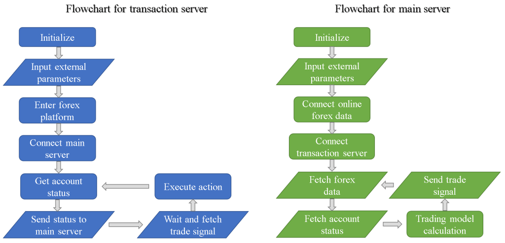
Figure 2. Program flowchart for transaction and main server.

Trading Strategy

In this project, a simple strategy for trading is implemented for verification of the effectiveness of automated trading (see another project <reinforcement learning assisted forex trading> for in-depth investigation on trading strategies):

1. The account initially buys a currency pair at a random point.
2. If the rate increases and reach the take profit value, sell it.
3. If the rate decreases and drops below a defined value, buy twice the previous amount.

Figure 3. Trading strategy used in this project.

As long as the rate reaches the take profit point within the period of a trade, this strategy will always be profitable (though in reality this strategy has several disadvantages and runs at the risk of a stop out due to the absence of a stop loss). By using this strategy, the system can be tested of functionality since it requires every functional block to work properly.

Trading Results on Real Account

After testing a few times on a demo account, I decided to use a real account so that I can obtain practical experience being a real game player, and also be stimulated for all the amount I had invested. The initial balance is set as 500 USD ($) to give me enough capital to test this system, but not too much for losing all hope if I ever get stopped out (Fortunately, this never happened.).

The detailed trading results using a real account between 2018/05/04 and 2019/03/12 can be downloaded here. The major currency pairs are used, and a multiplier of 50 (or leverage of 2%) is used to magnify the trade profit and loss. Table 1 and 2 summarize the overall results.

Table 1. Currency pairs used for trading and their corresponding trade count.

Currency Pair Trades
EUR/USD99
NZD/USD60
AUD/USD75
GBP/USD86
USD/JPY66
USD/CHF28
USD/CAD52
Total466

Table 2. Summary for real account trading using the automated system.

Start Time PointApr 5 2018 11:05
End Time PointMar 12 2019 8:52
Total Trade Amount ($)17074
Total Received Amount ($)17234.26
Total Profit ($)160.26
Average Profit per Trade ($) 0.344

Fig. 4 shows the account balance and profit during the whole period. For the first 396 trades, the balance rises in a slow and steady manner. The 397th trade, which is the trade resulting in a sharp decline of balance, is actually manually closed by myself due to reason that it got stuck in a losing position for too long. I had to close it myself so for maintaining enough equity to keep trading. This clearly demonstrates the disadvantage of the trading strategy I had used. From the 398th to the 597th trade, I increased the buy amount so that a larger change in balance (either gain or loss) is exhibited. At last, the balance arrives at 660.26$ and a total profit of 160.26$ is acquired.

Figure 4. Balance and profit vs trade count (the i-th trade).

Summary

In summary, an automated forex trading system is developed and has several features including automatic transaction, forex history data storage, real-time data acquisition and trading model implementation. This system is comparable with another electronic trading platform MetaTrader, however still lacking several other features such as visualization of forex data or economic calendar analysis. I am planning to integrate this system with another project <reinforcement learning assisted forex trading> for optimizing the trading strategy.

Automated Microfluidic Controlling Platform

I have always wanted to automate the cumbersome experimental operation process. For biochemical experiments, often a whole day in web lab is spent in order just to acquire one single set of data. Having the hands-on experience of developing hardware and software integrated systems for several projects (e.g. Surface Plasmon Resonance Platform, Real-time Impedance Detection Systems), I initiated this project for constructing a microfluidic controlling platform that can automatically manipulate liquid-based solutions of little volume, and also assist real-time detection experiments.

Platform Structure

The platform is constructed by four sections: A Raspberry Pi, an actuator module that consists of an Arduino and two H-bridge circuits, a fluid controlling system made up of a syringe pump/syringe device, and the microfluidic platform (Fig. 1).

Figure 1. System architecture of the automated microfluidic controlling platform.

Here, the Raspberry Pi serves as the main processing unit, which an Apache web server is constructed on, and is used to communicate with a remote user by website. The front-end of the website is designed using HTML, Javascript and CSS, and the back-end is designed using PHP. Javascript and PHP communicate using jQuery, and the PHP code is written for controlling peripheral devices.

For x/y position control, the Raspberry Pi sends data through type-B USB to the Arduino, which afterwards commands the H-bridge circuits, then control the x/y stepper motors on the microfluidic platform for moving the position of the racket. The servo motor is used to control the high/low position of the tube it holds, where the high (low) position means the tube isn’t (is) inserted into the microtube (Fig. 2).

Figure 2. The microfluidic platform and surrounding modules.

For fluid control, the Raspberry Pi sends an infuse/withdraw signal to the syringe pump using another type-B USB, which subsequently pushes/pulls the syringe on it. A simple flow for moving liquid from microtube A to microtube B is:

1. Confirm that the tube (for fluid conveyance) position is high. If not, then move it up by servo motor.
2. Move to microtube A by stepper motor.
3. Change tube position to low by servo motor.
4. Withdraw liquid by syringe pump.
5. Change tube position to high by servo motor.
6. Move to microtube B by stepper motor.
7. Change tube position to low by servo motor.
8. Infuse liquid by syring pump.

Hardware Development

Fig. 3 shows a photograph of the whole platform. For the microcontrollers, Raspberry Pi 3 B+ and Arduino Uno are used. For the H-bridge, L298N dual driver module is used. Legato® 111 syringe pump (kd Scientific) and Series 700 Microliter syringe (Hamilton) are used for fluid control. HMS-25BY46L38 stepper motors and an SG90 servo motor are used for the microfluidic platform.

Figure 3. Photograph of the automated microfluidic controlling platform.

The circuitry for this platform is relatively easy compared with other projects (e.g. Aroma Alarm Clock), and is consisted simply with wires and resistors. Except the motors and the racket with microtubes, all the other components of the for microfluidic platform are fabricated using 3D printing. 3D-printed gears are fixed with the stepper motors. Precise control of racket position (~ 0.2mm) is realized by combining the gears with a 3D-printed linear gear that fits on the racket and another linear gear of a subsidiary platform which the racket sits on. Below is a clip demonstrating how the 3D-printed components, the stepper motors, the racket with microtubes, and a microfluidic electrode chip are integrated together, along with x/y position control of the racket.

Software Development

The program structure written inside Raspberry Pi is quite similar to the program structure in another project “Real-time Impedance Detection Systems”. The difference for this project is that PHP is used to directly communicate with peripheral devices (Fig. 1).

Fig. 4 displays the website-based user interface for controlling this platform. The UI is divided in four sections: procedure window, buttons field, racket window, and status window. Briefly, the user can save/load settings from the connected Arduino, add/delete a control command, start/pause/stop the current procedure, download the control procedure to a text file, and append a command after another one.

Figure 4. Website user interface of the platform.

Fig. 5 shows the settings menu. Here, the user needs to find the device url for Arduino and the syringe pump beforehand and insert them. Several controlling preferences, such as motor operation delay time, steps for the stepper motor to move per cell (microtube), precise high/low position of the servo motor, current cell of the racket … etc. can be set.

Figure 5. Settings menu of the UI.

Fig. 6 shows the add command menu. The user can either move the stepper motor to a target cell (microtube), infuse/withdraw fluid at a self-defined rate and target volume, move servo high/low position, or perform a time delay.

Figure 6. The add command menu of the UI.

Concentration Gradient Generation

An automated concentration gradient generation process is written, and is carried out by the automated platform. Here is a clip for demonstration (speed = 10x):

Real-time Impedimetric Detection

The tube doesn’t have to directly connect to a syringe. A detection chip can be inserted between for real-time detection of different solutions (similar to the method illustrated in Fig. 1 of another project Surface Plasmon Resonance Platform). A microfluidic interdigitated electrode chip using microfabrication technique is previously developed (which is a part of my research), and is used for detection of electrochemical impedimetric properties of the fluid. Here, potassium ferricyanide (K3Fe(CN)6) and potassium ferrocyanide (K4Fe(CN)6) are serial diluted using the platform, and real-time impedance detection is carried out using an electrochemical analyzer (CHI614b, CH Instruments) and the microfluidic chip.

Fig. 7 shows the detection result. It can be seen that the solution switching time is relatively fast and stable, and the detection time is consistent, which demonstrates the advantages of this automated platform.

Figure 7. Real-time impedimetric detection plot for different diluted concentrations of K3Fe(CN)6/K4Fe(CN)6.

Summary

In summary, a website-controlled automatic microfluidic controlling platform is designed and fabricated for real-time microfluidic sensing and other applications. Solution manipulation using this platform is stable, repeatable, and time-saving compared with manual operation.