This is a project which I and my classmates had finished in a course focusing on practical implementation for mechatronics and system design, and is a sequel of the previous Aroma Alarm Clock project. We designed an Android app-controllable alarm clock which can heat up objects such as a water-filled container, and intend to further improve it for making coffee, so that one can enjoy a fresh cup of coffee in the morning after awakening. Similar to the previous one, I worked as the engineer in our group, and designed and constructed the hardware system.
System Framework
Fig. 1 shows the overall system architecture, which several electronic components (e.g. clock module, LCD display…) are controlled by a microcontroller that can communicate with a mobile application using a Bluetooth module. The alarm clock can be controlled either using its own hardware input (buttons) or using the mobile app. Simply put, the system has same the functions as a typical alarm clock, but has two additional features:
1. Temperature controllable heater. 2. Bluetooth communication.
Figure 1. System architecture for the coffee maker alarm.
Hardware
Arduino Uno, DS1302 chip, HC-06 and LCD1602 are used respectively for the microcontroller, real-time clock module, Bluetooth module and LCD display module. Being an end-semester project in class, the components are simply connected using a breadboard. All the hardware components except the heater are packed using patterned cardboard in a simply looking fashion (Fig. 2).
Figure 2. Hardware appearance of the coffee maker alarm.
A ceramic heater plate and temperature sensor are integrated for realizing temperature controlling (Fig. 3), and are connected out from the main hardware. The total cost for all the components is 1,741 NTD (≅ 60 USD).
Figure 3. Heater and temperature sensor.
Software
App Inventor 2 is used as the platform for creating the Android app for controlling the hardware. Fig. 4 displays the designing interface for the mobile app using the platform.
Figure 4. Design interface using App Inventor 2.
The coding section for this platform is very unique and easy to get started. It implements a block-based programming method which developers can create procedure by dragging pre-defined blocks together to for performing a certain function. Developers with no programming background can use this kind of environment for creating mobile apps. Fig. 5 shows a gallery containing the complete code for the alarm clock controlling app.
Figure 5. Gallery of block codes for the alarm clock app.
Here’s a video demonstration for using this system:
I have always wanted to automate the cumbersome experimental operation process. For biochemical experiments, often a whole day in web lab is spent in order just to acquire one single set of data. Having the hands-on experience of developing hardware and software integrated systems for several projects (e.g. Surface Plasmon Resonance Platform, Real-time Impedance Detection Systems), I initiated this project for constructing a microfluidic controlling platform that can automatically manipulate liquid-based solutions of little volume, and also assist real-time detection experiments.
Platform Structure
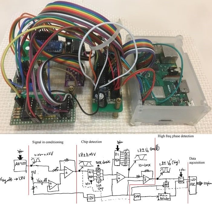
The platform is constructed by four sections: A Raspberry Pi, an actuator module that consists of an Arduino and two H-bridge circuits, a fluid controlling system made up of a syringe pump/syringe device, and the microfluidic platform (Fig. 1).
Figure 1. System architecture of the automated microfluidic controlling platform.
Here, the Raspberry Pi serves as the main processing unit, which an Apache web server is constructed on, and is used to communicate with a remote user by website. The front-end of the website is designed using HTML, Javascript and CSS, and the back-end is designed using PHP. Javascript and PHP communicate using jQuery, and the PHP code is written for controlling peripheral devices.
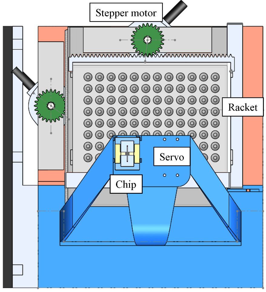
For x/y position control, the Raspberry Pi sends data through type-B USB to the Arduino, which afterwards commands the H-bridge circuits, then control the x/y stepper motors on the microfluidic platform for moving the position of the racket. The servo motor is used to control the high/low position of the tube it holds, where the high (low) position means the tube isn’t (is) inserted into the microtube (Fig. 2).
Figure 2. The microfluidic platform and surrounding modules.
For fluid control, the Raspberry Pi sends an infuse/withdraw signal to the syringe pump using another type-B USB, which subsequently pushes/pulls the syringe on it. A simple flow for moving liquid from microtube A to microtube B is:
1. Confirm that the tube (for fluid conveyance) position is high. If not, then move it up by servo motor. 2. Move to microtube A by stepper motor. 3. Change tube position to low by servo motor. 4. Withdraw liquid by syringe pump. 5. Change tube position to high by servo motor. 6. Move to microtube B by stepper motor. 7. Change tube position to low by servo motor. 8. Infuse liquid by syring pump.
Figure 3. Photograph of the automated microfluidic controlling platform.
The circuitry for this platform is relatively easy compared with other projects (e.g. Aroma Alarm Clock), and is consisted simply with wires and resistors. Except the motors and the racket with microtubes, all the other components of the for microfluidic platform are fabricated using 3D printing. 3D-printed gears are fixed with the stepper motors. Precise control of racket position (~ 0.2mm) is realized by combining the gears with a 3D-printed linear gear that fits on the racket and another linear gear of a subsidiary platform which the racket sits on. Below is a clip demonstrating how the 3D-printed components, the stepper motors, the racket with microtubes, and a microfluidic electrode chip are integrated together, along with x/y position control of the racket.
Software Development
The program structure written inside Raspberry Pi is quite similar to the program structure in another project “Real-time Impedance Detection Systems”. The difference for this project is that PHP is used to directly communicate with peripheral devices (Fig. 1).
Fig. 4 displays the website-based user interface for controlling this platform. The UI is divided in four sections: procedure window, buttons field, racket window, and status window. Briefly, the user can save/load settings from the connected Arduino, add/delete a control command, start/pause/stop the current procedure, download the control procedure to a text file, and append a command after another one.
Figure 4. Website user interface of the platform.
Fig. 5 shows the settings menu. Here, the user needs to find the device url for Arduino and the syringe pump beforehand and insert them. Several controlling preferences, such as motor operation delay time, steps for the stepper motor to move per cell (microtube), precise high/low position of the servo motor, current cell of the racket … etc. can be set.
Figure 5. Settings menu of the UI.
Fig. 6 shows the add command menu. The user can either move the stepper motor to a target cell (microtube), infuse/withdraw fluid at a self-defined rate and target volume, move servo high/low position, or perform a time delay.
Figure 6. The add command menu of the UI.
Concentration Gradient Generation
An automated concentration gradient generation process is written, and is carried out by the automated platform. Here is a clip for demonstration (speed = 10x):
Real-time Impedimetric Detection
The tube doesn’t have to directly connect to a syringe. A detection chip can be inserted between for real-time detection of different solutions (similar to the method illustrated in Fig. 1 of another project Surface Plasmon Resonance Platform). A microfluidic interdigitated electrode chip using microfabrication technique is previously developed (which is a part of my research), and is used for detection of electrochemical impedimetric properties of the fluid. Here, potassium ferricyanide (K3Fe(CN)6) and potassium ferrocyanide (K4Fe(CN)6) are serial diluted using the platform, and real-time impedance detection is carried out using an electrochemical analyzer (CHI614b, CH Instruments) and the microfluidic chip.
Fig. 7 shows the detection result. It can be seen that the solution switching time is relatively fast and stable, and the detection time is consistent, which demonstrates the advantages of this automated platform.
Figure 7. Real-time impedimetric detection plot for different diluted concentrations of K3Fe(CN)6/K4Fe(CN)6.
Summary
In summary, a website-controlled automatic microfluidic controlling platform is designed and fabricated for real-time microfluidic sensing and other applications. Solution manipulation using this platform is stable, repeatable, and time-saving compared with manual operation.
This project is an integration of computer vision, mechatronics, wireless communication (Bluetooth), database management, mobile app design, sensors and actuators, and is a final project of a course called Design of Automated Systems. I teamed up with two classmates for accomplishing this challenging task of constructing a remote commandable car that can automatically detect and find balls with different colors, then be manually navigated towards a certain location. My contributions to this project are coding the ball-tracking algorithm using OpenCV, utilizing the microcontroller Arduino for movement control, and wiring electric components to the hardware circuit (yellow shaded area in Fig. 1).
System Architecture
Fig. 1 illustrates the system architecture for this project. Raspberry Pi is used as the main computer. Node.js is installed for communicating with the MariaDB database, receiving ordering signals from a remote Android app, and commanding the ball-tracking C++ program.
Figure 1. System architecture of the remote commandable self-driving toy car.
A standard procedure for command and action of the system is as follows.
Android user logins to Node.js server by verification of username and password through the database.
The user sends target ball color to the server.
The server sends command to “face_ball” program by bash.
“face_ball” detects colored ball position by ball recognition algorithm.
“face_ball” sends command to Arduino by serial USB.
Arduino controls two servo motors for the car to move towards the target ball.
After getting close enough, a fence is set to physically trap the ball.
Hardware Design
Fig. 2 shows a 3D drawing of the toy car. Components such as Arduino, Raspberry Pi (RPi) are fixed to the laser-cut acrylic board using plastic columns. Here, three servo motors are used. The first two controls the left/right wheel, and the third controls a trap that can lock the ball at the front of the car.
Figure 2. 3D illustration of the remote commandable toy car.
Figure 3. Preliminary version of the toy car.
Ball-Tracking Program
The main objective of the ball-tracking program is to navigate the toy car towards a target ball, and trap it with a fence connected to the toy car. The flowchart for image recognition of the ball is shown in Fig. 4.
Figure 4. Flowchart for the ball detection algorithm.
Using the above algorithm, rapid detection of the target ball can be realized. Here’s a demonstration of the program recognizing a ball being thrown in the air in real-time.
For movement control of the toy car, the Arduino will either turn left, turn right, or move straight according to the control algorithm shown in Fig. 5.
Figure 5. Flowchart for the ball-trapping algorithm.
Fig. 6 shows the commands available for controlling the toy car using Arduino.
Figure 6. Available commands for Arduino.
Here’s a clip for automated control of the toy car. A red ball is defined as the target and is trapped by the car using a fence.
Android App Design
The app is designed using MIT App Inventor, which implements a block-based programming method in which developers can create procedures by dragging predefined blocks together to for performing a certain function. Fig. 7 shows an image containing the complete code for the Android app. The user interface and flowchart for direct control of the toy car is shown in Fig. 8.
Figure 7. Complete block code for the Android app (click for magnified view).
Figure 8. App interface (left) and Arduino control flowchart (right).
Here’s a demonstration for the remote commandable toy car. The car automatically detects a green ball, moves near, and traps it. Then it is manually controlled to avoid obstacles and reach a yellow-colored area at the end.