Electrochemical Impedance Modeling Programs

I started to use a technique called electrochemical impedance spectroscopy (EIS) for biosensing since my undergraduate research. For analyzing EIS data, an equivalent circuit must be constructed for modeling the reaction mechanism. Physical parameters can be extracted by fitting the data using the model. However, for most software, the circuit elements being provided and their corresponding combined circuit couldn’t necessarily meet my needs for finding the physical parameters in a symmetric electrode system. Therefore, I developed a circuit fitting program for customized analysis of impedance data. The fitting and impedance calculation program are used in a first-author journal paper of mine. In the following paragraphs, the development of the fitting program, another program that assists data visualization, and a program for calculating the diffusion impedance of interdigitated array (IDA) electrodes are detailed.

Figure 1. (a) The Nyquist plot for visualizing impedance values, and (b) an equivalent circuit with several circuit elements for modeling electrode surface reactions.

Electrochemical Impedance Circuit Fitting Program

The algorithm for finding all the element parameters in a given circuit is by implementing the Levenberg-Marquardt non-linear fitting method. This is a general and popular method for solving the minimum value of function E(x), where

$$E(x)={1 \over 2} \sum_{i=1}^m [f_i(x)]^2 $$

For impedance data fitting, a complex non-linear least square process (CNLS) is implemented, and the above equation can be specialized as

$$S=\sum_{i=1}^{N_f} [w_{i,\mathrm{Re}}( \mathrm{Re}(Z_{i,cal}) – \mathrm{Re}(Z_{i,exp}) )^2+w_{i,\mathrm{Im}}( \mathrm{Im}(Z_{i,cal}) – \mathrm{Im}(Z_{i,exp}) )^2]$$

where S is the weighted sum of squares of error, Nf is the number of frequencies within an experiment, Zi is the impedance of the i–th frequency, and wi,Re and wi,Im are the statistical weights for the real and imaginary parts of the impedance of the i–th frequency. The subscript exp indicates experimental value and the subscript cal indicates the calculated value while fitting.

For any kind of circuit, Zi,cal can be calculated by the set of element parameters and the frequency (e.g. R for a resistor, C and f for a capacitor), then S can be calculated using its defined equation. By minimizing S, the fitted element parameters can be modified so that the result impedance (Zi,cal) can be as close as possible to the experimental value (Zi,exp). Fig. 2 shows an example for a non-linear curve fitting process.

Figure 2. A non-linear curve fitting process (source: https://en.wikipedia.org/wiki/Gauss%E2%80%93Newton_algorithm).

A program written in C language is designed using the open-source numerical analysis library ALGLIB® to implement numerical integrations and calculations. ALGLIB is also used for non-linear least squares fitting of EIS data using Levenberg-Marquardt method. Several circuit elements for EIS data fitting are available in this program, which are shown in Table 1. Detailed methods for calculating the IDA diffusion element is shown in my first-author paper.

Table 1. Available circuit elements in the fitting program.

A circuit description code is defined to express equivalent circuits. Elements, including whole blocks inside parentheses, are either in series or parallel with each other. Those inside an odd number of pair of parentheses are in parallel with each other, and those inside an even number of pair of parentheses are in series. Fig. 3 shows a circuit equivalent to the description code of “R(RC)(R(RC))”.

Figure 3. Circuit description code and its corresponding circuit. Equivalent parts are marked by identical colored blocks.

Figure 4. Snapshot of the equivalent circuit fitting program.

[Download equivalent circuit fitting program (Runs on Windows 64-bit environment)]

[Source code for the equivalent circuit fitting program]

Real-time Impedance Plotting Program

It is reasonable that an element in a circuit contributes to the impedance change to a certain degree. For instance, a resistor has an influence on the real part of impedance, and a capacitor affects its imaginary part. However, when the circuit consists of elements with serial or parallel combinations, it can be quite difficult to imagine how the shape of impedance data would change according to each element.

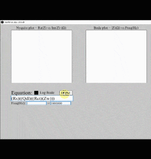
Therefore, I wrote a program for plotting impedance data in real-time using Processing language. After entering the circuit description code into the program, a Nyquist plot, total impedance Bode plot, and phase angle bode plot is generated. The user can use horizontal bars to control the value of a specific element. By changing its value, the impedance would be calculated immediately, and the plot would be drawn out in real-time.

Figure 5. User interface for the real-time impedance plotting program.

Here’s a clip for demonstrating the real-time impedance plotting program.

[Source code for real-time impedance plotting program]

IDA Diffusion Impedance Calculation Program

The IDA diffusion element is a novel element for parameterizing the diffusion impedance of an IDA electrode using its shape factor (we/w), magnitude of the admittance (Y0), and the dimensionless frequency (w2ω/D). However, complex functions are required for calculating its value, such as the Bessel function, the complete elliptic integral of the second kind, and definite integrals.

Due to calculation difficulties, a program is written for calculating the IDA diffusion impedance. The program consists of two files “settings.txt” and “IDA_diff_Z.exe”. “settings.txt” is of the format below:

These contain all the 12 parameters for the usage of this program. A detailed description is listed in order below:

  1. If [output to txt file] is 0, then calculated impedances will be shown directly on screen. If it is 1, then the values will be saved to the file “Z_diffusion_IDA.txt”.
  2. The maximum frequency for impedance calculation can be set after [max freq (Hz)].
  3. The minimum frequency for impedance calculation can be set after [min freq (Hz)].
  4. The number of frequency points within a decade can be set (e.g. If [points per decade] is set to 5, then frequencies calculated between 101 and 100Hz will be 101, 100.8, 100.6, 100.4, 100.2 and 100Hz.)
  5. we can be set after [electrode bandwidth we (um)].
  6. wg can be set after [gap width wg (um)].
  7. l can be set after [electrode length l (mm)].
  8. N can be set after [number of bands N].
  9. D can be set after [diffusion coefficient D (m^2/s)].
  10. C* can be set after [bulk concentration C* (mM)].
  11. n can be set after [number of electrons n].
  12. T can be set after [temperature T (K)].

After setting the 12 parameters, put “settings.txt” and “IDA_diff_Z.exe” in the same directory and open “IDA_diff_Z.exe”. Impedances will be automatically calculated and printed in the defined format (Fig. 6). ※The program can only be run in a Windows 64-bit environment.

Figure 6. An example output of the IDA diffusion impedance calculation program.

[Download IDA diffusion impedance calculation program]

Minesweeper AI

I got addicted to Minesweeper the first few days when I started playing this awesome puzzle game. Solving the game faster every few times gives me great satisfaction of self-fulfillment. However, for the “expert” board setting, where 99 mines are hidden within a 16×30 square grid, I had never obtained a score lower than 100 seconds. Curious of what the fastest solving rate is the one can achieve, I designed a Minesweeper AI program that can automatically play the Windows Minesweeper game.

C language is used for programming, and the algorithm flowchart is displayed in Fig. 1.

Figure 1. Algorithm flowchart of the Minesweeper AI program.

Here breadth-first-search (BFS) is used to search for uncovered squares on the grid, and a queue is used for saving uncovered squares to be analyzed. A game-playing optimized algorithm is written inside the program, and OpenCV is used to take a snapshot of the Minesweeper window region and process the image for subsequent calculations. Mouse movement and click actions are realized by including the windows.h header.

The usage of the program is relatively simple. The user should only execute the Minesweeper game program, and modify the game setting beforehand. After opening the AI .exe file, the program will automatically locate the Minesweeper game, calculate the dimensions, then start playing. If a mine is accidentally clicked, the program will continue to play the next game until a fully uncovered board is achieved.

Here is a clip demonstrating the Minesweeper AI playing an expert level game and winning in 7 seconds. It failed on the first try almost at the end, but succeeded on the second try.

[Download program for the Minesweeper AI (Can only run on a windows 64-bit OS)]

Miniaturized ELISA Platform

Studying in a cross-disciplinary department meant having the freedom to choose what to explore. I entered the intelligence bio-sensing lab (previously named bio-molecular device lab) hosted by professor Lin-Chi Chen when I was a junior. There I was trained how to put into practice the engineering skills that I have learned during college, and implementing them on biosensing. I became interested in manufacturing devices that can realize automation, assist research, or help reduce the cost for lab experiments (e.g. Real-time Impedance Detection Systems, Surface Plasmon Resonance Platform, Automated Microfluidic Controlling Platform). This miniaturized ELISA platform serves as the first one among those devices and systems I had created.

The enzyme-linked immunosorbent assay (ELISA) is a commonly used analytical biochemical assay that uses antibodies against the protein to be tested to detect the presence of ligands (usually proteins) in the liquid sample. However, the traditional method for performing this assay is costly and time-consuming. Therefore, I decided to construct a miniaturized ELISA platform that can help reduce sample usage, and thus make it cheaper.

Small circular holes are cut on a thin acrylic board are by laser cut, a holder for assisting supporting the microwell is fabricated using 3D printing, and PVDF films are used as the base material for protein immobilization (Fig. 1).

Figure 1. Materials used for the miniaturized ELISA platform

The acrylic board with holes and another board with no holes are used to clip the PVDF film tight, wrapped with tape, making microwells with a volume capacity of ~10μL (Fig. 2 left). The microwell is put on the 3D-printed holder, and the right picture of Fig. 2 shows the microwell platform with each well containing 10μL deionized water.

Figure 2. PVDF clipped with an acrylic board with holes and another board without holes (left), and the microwell platform with every well containing 10μL deionized water.

Streptavidin-HRP is diluted using PBS buffer, and 5μL of the solution is added in each of the microwell. Then 5μL TMB is added for validation of the colorimetric detection method. Fig. 3 shows the experiment result using the platform for qualitative analyzing different concentrations of streptavidin-HRP. It can be seen that different concentrations yield different intensities of absorbed light signals (λ = 450nm), thus this platform can be further improved for real experimental use.

Figure 3. Different concentrations of streptavidin-HRP with TMB for colorimetric detection using the miniaturized ELISA platform.

This project is the first one for me to implement simple skills that I have learned during the first three years in university on real bio-detection research issues, which motivated me to start thinking of practical methods to use engineering techniques for solving problems in an interdisciplinary way.

Linear Algebra Calculation using Integrated Circuits

Even the simplest thing we recognize may seem increasingly difficult in another point of view. Take a simple arithmetic operation for example, if one wants to calculate the function y = ax + b with given a and b, he simply multiplies any number x with a, then adds b, and gets the answer. What if no multiplication and addition can be used? How can the calculation even be possible?

Computers can actually finish the task by implementing three fundamental logic operations: AND, OR, and NOT. Most of them can do these operations within a nanosecond. In this project, I constructed a circuit for performing a simple linear algebra calculation (Fig. 1) using only basic logic and storage circuits (Fig. 2) that can be realized using standard cells.

Figure 1. Formula to be calculated. (x0, x1, x2 are all 6 bit 2’s complementary integers)

Figure 2. Basic logic and storage circuits. (Note that other circuits (e.g. NAND, XOR) are also used in this project)

Here, x0, x1 and x2 equal the three 6-bit integer inputs (2’s complementary), so there are a total of 18 Boolean input values. The output is stored in a 16-bit integer. Therefore, the goal for this project is to construct a circuit that connects all of the 18 inputs and the 16 outputs, and perform the calculation.

To make it harder, three stages of pipelines are carried out. This means that calculations are divided into three parts, and the most time-consuming part contains the critical path of the whole circuit. Fig. 3 shows an illustration of the designed circuit.

Figure 3. Logic circuit diagram for realizing the arithmetic operation (Fig. 1) of this project.

Verilog is used for simulating the results, and the circuit is written as a spice sub-circuit model. Because the D flip-flop is used, the critical time is defined as the clock cycle of the D flip-flop. Moreover, the number of transistors are defined for every basic logic circuit, so the total number of transistors can be calculated, and is named the “area” of the whole circuit.

Fig. 4 shows the simulation results of the circuit. It can be seen that only 1.3305 nanosecond is used for a half clock cycle of the circuit. This means that the circuit can continuously output calculation results every 2.661 nanosecond, which is really fast!

Figure 4. Simulation results using Verilog.

Having the experience of using absolutely no arithmetic operations for calculating a linear algebra problem really significantly broadened my insight towards digital IC design. This project inspired me to understand that even the most insignificant elements possess the potential to be combined and make up the world that we live in.

[Verilog Source Code for Logic Circuit]

Robot Arm Control

It’s easy for us to point at a certain coordinate in space. That’s mainly because we simply locate the point with our eyes, and continuously check if our finger is pointing at that very spot. It surely will be more difficult without using eyes, and this is the case for robot arm control with no image feedback.

Think of a two arm robot (Fig. 1). We usually want to reach a certain point on the x-y plane. The problem is only the angle of the joints can be controlled. How can we correlate the joint angles of a robot with its tip coordinate? Things get harder when it comes to 3D space, and even harder considering its rotation.

In this project, I created a program that can calculate the every joint angle of the 6-arm robot IRB140 for positioning it at a given (x, y, z) coordinate and rotation.

Figure 1. Dimensions of the IRB140 robot (unit: mm) [1].

The problem for reversing an operation from the specified coordinate and rotation to every rotation angle of an arm joint lies in the field of inverse manipulator kinematics. There may be multiple solutions that lead to the same result. Thus, I implemented the Pieper’s solution [2] for solving the joint angles for the IRB140 robot.

Here’s a video demonstration for precision control of the IRB140 by only giving the joint angles as the input. The robot follows a trail surrounding a paper box with the tip of the last arm always pointing at the center of the box.

[Source code for robot arm control program]

1. ABB, IRB140 product specification, 2019, https://library.e.abb.com/public/2893a5756d204e19aba0d37c2a2cadc6/3HAC041346%20PS%20IRB%20140-en.pdf
2. Craig, J.J., Introduction to Robotics: Mechanics & Control. 1986: Addison-Wesley Publishing Company.